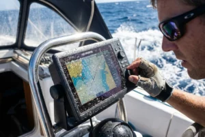
Most electrical upgrades on a cruising boat add capacity to the house bank. The VHF, AIS, chart plotter, navigation lights, and bilge pump usually draw from that same bank, so a failure takes them all out together. A redundant marine electrical system for sailboats gives those few critical loads a second power path that does not depend on anything in the first one.
This article covers the planning and wiring logic: what to protect, how to size a separate emergency battery, how to connect it, how to fuse it, and how to prove it works by deliberately breaking the main system at the dock. It does not recommend products. The design applies whatever brands you already own.
The failures that take out safety gear all at once
A second battery only helps if you know which failures it has to survive. Most of these are ordinary faults, and all of them are common on boats that are well maintained in every other way:
- A dead or damaged house bank. Deep discharge, a failed cell, or a bank that has aged out. Everything on it goes dark together.
- A lithium bank that disconnects itself. The battery management system opens a protective switch for overcurrent, overtemperature, or low cell voltage. The bank vanishes from the circuit instantly, mid-passage, with no gradual dimming to warn you. It can also leave an alternator with nothing to charge, which can damage the alternator or its regulator unless the system is set up for that case. Check your charging equipment’s documentation.
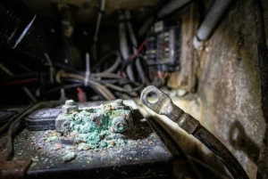
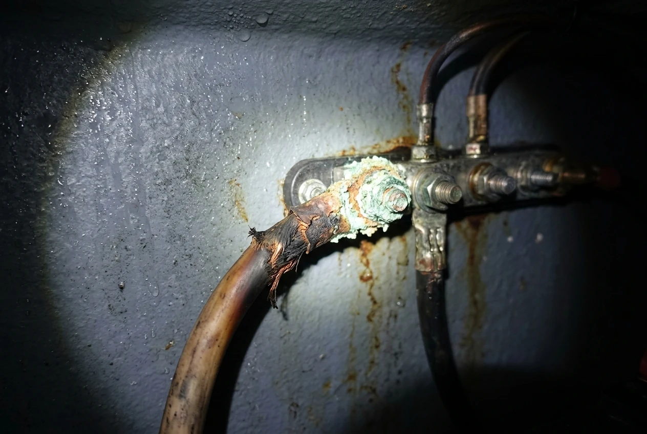
- A corroded or loose bus bar or terminal. Resistance builds up at a connection, voltage drops under load, and eventually the connection fails or overheats. Because the bus bar feeds many circuits, one bad joint can drop several devices at once.
- A single blown main fuse or tripped main breaker. If every load sits downstream of one protective device, a short anywhere upstream of the branch fusing interrupts them all.
- A battery switch in the wrong position. Someone turns it to Off while working on the boat, or leaves it on a single bank that has since run flat.
- Alternator or regulator failure. The house bank drains while you run the engine, and you do not notice until the voltage is low.
These faults usually come from shared parts: one bank, one bus, one main fuse, one switch. Redundancy means removing the shared parts for a short list of loads.
Deciding what counts as a critical load
Start with a written list. A load is critical if losing it in an emergency changes whether you can be found, avoid a collision, keep the boat afloat, or call for help. For most offshore and coastal cruising boats, that list looks like this:
- VHF radio, including its connection to a GPS source if you use DSC calling
- AIS transponder or receiver
- One chart plotter, or a single navigation display
- Navigation lights, including the masthead tricolor or anchor light if you have one
- Automatic bilge pump and its float switch
- Emergency communications such as a satellite communicator that charges from the boat’s power
- Cockpit or instrument lighting you need to run a watch
Leave out refrigeration, water maker, autopilot (unless you cannot steer without it), entertainment, and the inverter. Those can fail without the boat becoming unsafe, and including them is how an emergency circuit grows until it is no longer an emergency circuit.
To see what each device offers in a distress situation, the article on marine VHF radio features for emergencies covers what to look for in the radio itself. For this exercise, you only need to know what the radio draws.
Total the draw before you buy anything
For each device on the list, find the current draw in its manual or on its label, or measure it with a DC clamp meter or an inline shunt. Record two numbers where they differ: the normal running draw and the peak draw. A VHF draws far more when transmitting than when listening, and a bilge pump draws far more than its idle zero. Navigation lights and AIS run continuously at night, so they dominate the overnight total.
Then work through three calculations:
- Continuous load in amps. Add up the devices that run constantly during a night passage.
- Amp-hours for your target duration. Multiply the continuous amps by the hours you want the system to last. A common target is a full night plus a margin, and many sailors choose 24 hours so the emergency battery covers a night watch, a day of limping toward a harbor, and a second night.
- Peak current. Add the worst-case simultaneous draw: transmitting, pump running, lights on. This sets the fuse size and wire gauge, not the battery capacity.
For illustration only, using round numbers, you must replace with your own readings: if the continuous night load came to 4 amps, a 24-hour target would require 96 amp-hours of actual use. A lead-acid battery shouldn’t run much below half capacity if you want it to last, so you would shop for something close to twice that figure. A lithium chemistry allows deeper use, but follow the manufacturer’s figures for usable capacity and low-voltage cutoff.
Adding margin for battery aging and cold weather makes sense. A battery that tests at its rated capacity at purchase will not do so in five years.
A separate emergency battery, and why it needs its own charging path
The emergency battery is a dedicated battery, sized by the calculation above, that feeds only the critical loads. Its job is to remain full when the house bank is not, so the most important design decision is how it charges.
If the emergency battery is wired in parallel with the house bank and charged by the same alternator and charger outputs, it is exposed to the same failures. A shorted house bank pulls it down. A runaway charger overcharges both. A discharged house bank draws current from it. In that arrangement, you have a bigger bank, not a second one.
Better arrangements keep the emergency battery’s charge source separate from the house bank, or at least one-way:
- A small dedicated charger on shore power that keeps the emergency battery topped up at the dock.
- A small solar panel with its own controller, wired only to the emergency battery. This works at anchor and at sea, without involving the house bank.
- A one-way charge from the engine alternator or house bank, through a DC-to-DC charger or battery isolator, so current can flow into the emergency battery but never out of it into a failed house bank.
Whichever you use, the emergency battery should have a charging profile that matches its chemistry. A battery with a different chemistry from the house bank isn’t a problem if the charge source is separate. It is a problem if both share one charger set for the wrong type.
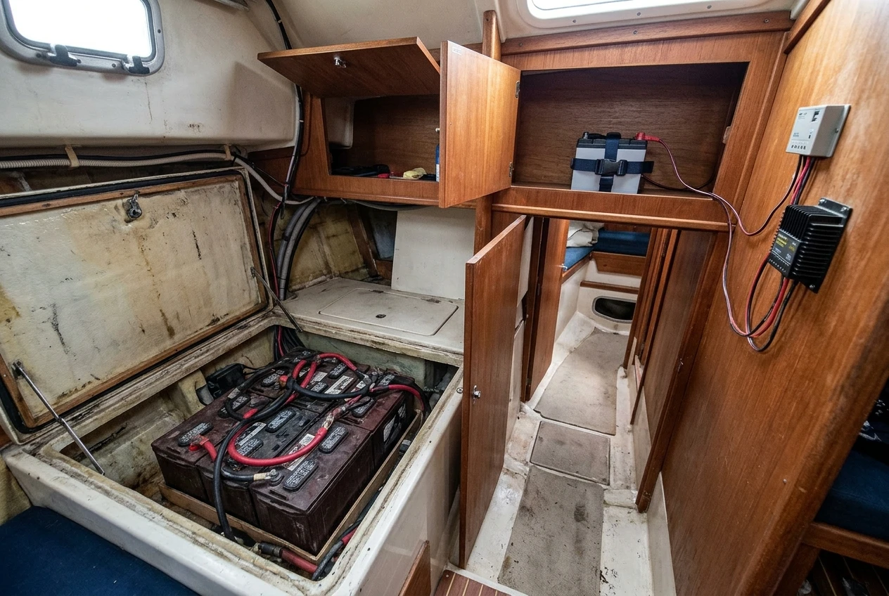
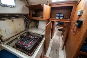
Mount the emergency battery away from the house bank, high and dry if possible, not in the same locker as the part most likely to flood or catch fire. Secure it so it stays put in a knockdown. If a fault does destroy the house bank compartment, the emergency battery should survive.
Cross-connect options and when each one fails
A cross-connect lets you use one battery to help the other: starting the engine from the emergency battery, or feeding the safety loads from the house bank when the emergency battery is low. There are three common ways to do it, and each fails differently.
Manual battery switch (1, 2, Both, Off)
This is the simplest option and the easiest to understand. You choose which battery supplies the boat.
It fails in two ways. The switch contacts can corrode or loosen, and it’s a single component that carries all the current for whatever it feeds. The more common failure is human: someone leaves the switch on Both, and a dead house bank drags down the emergency battery. Treat Both as a temporary position, and label it as such.
Emergency parallel switch
This is a dedicated switch, usually a momentary or latching solenoid type, that connects the two banks together only when you press it. Its main use is starting the engine from the emergency battery when the starting battery is flat.
It fails when the solenoid sticks closed, or the contacts weld after a heavy start, leaving the two banks permanently connected. Some versions need some voltage at their coil to operate, so a deeply discharged battery may not close them. Read the wiring diagram for your model and test it with a low battery, not just a charged one.
Automatic battery combiner
A combiner joins the banks when charging voltage is present and separates them when it is not. It suits the charging side of the system and requires no crew attention.
It fails when its sensing logic does something you did not expect. A badly discharged or shorted bank may connect at the wrong moment and pull the other down. The contacts can also fail closed, which leaves both banks permanently joined with no indication. Never rely on a combiner alone to protect the emergency battery. If you use it at all, use it only to charge the emergency battery from the engine alternator, and check periodically that it opens.
In practice, many boats use a combination: a one-way charge device for routine charging, plus a manual or emergency parallel switch for deliberate cross-connection. The crew then decides when to join the banks rather than leaving it to automatic logic.
Fusing, wire sizing and a dedicated safety bus
The wiring below decides whether a short in one circuit kills both power paths. The principle is that each battery has its own fuse, each fuse sits close to its battery, and the two feeds meet only at a controlled point.
One fuse per battery, close to the terminal
Put a fuse or circuit breaker on each battery’s positive lead as close to the terminal as practical. This protects the cable from the battery onward. If the cable shorts anywhere along its length, that fuse opens and only that battery is lost. For lithium batteries, which can deliver very high fault current, use a fuse rated for that interrupting capacity. Many installers specify a Class T fuse for this. Check the battery manufacturer’s recommendation.
The safety bus
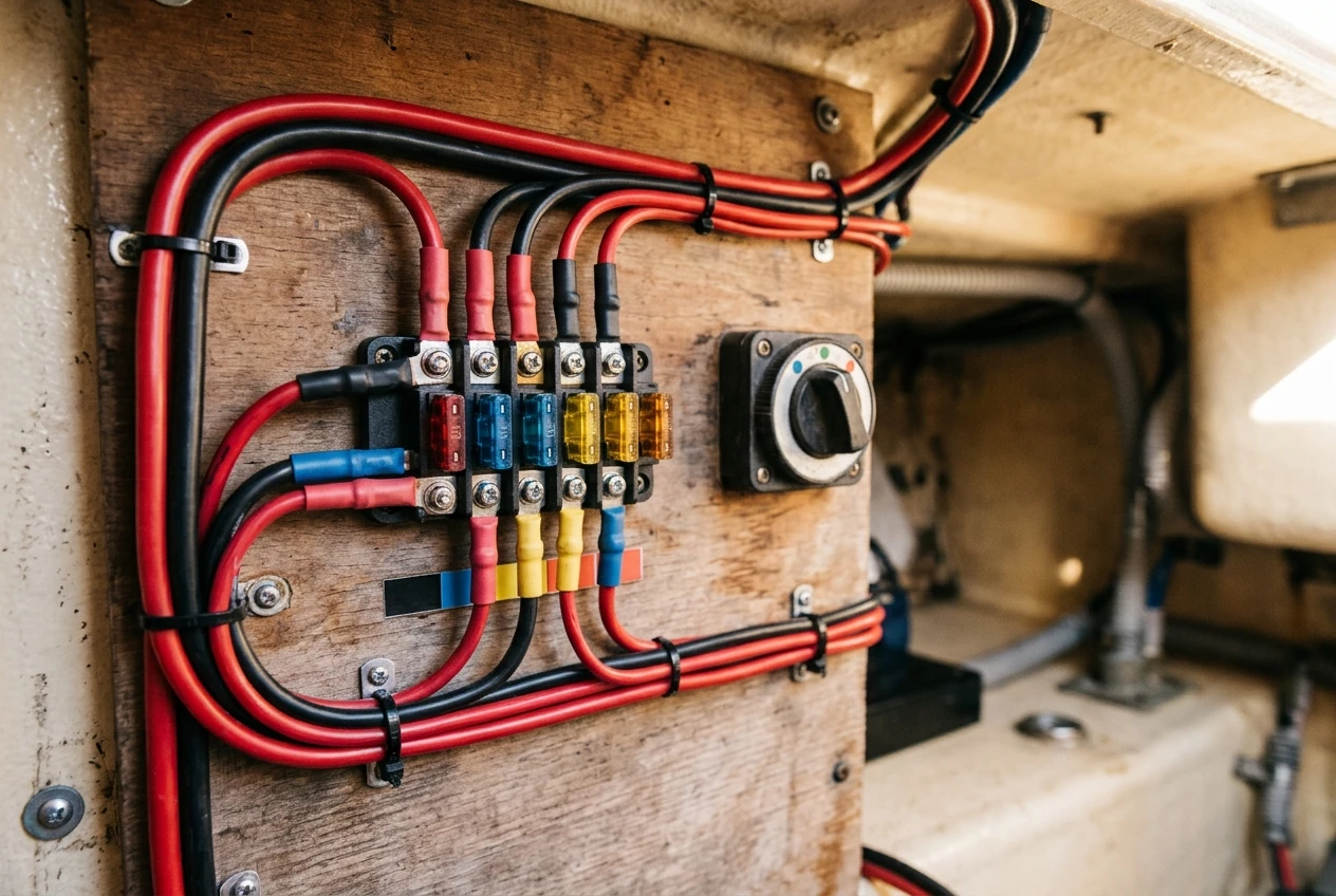
Run the emergency battery’s fused feed to a dedicated safety bus, which is a small fuse block or bus bar that carries only the critical loads. Each load gets its own fuse or breaker on that bus, sized for the wire it protects and not for the device.
You can feed the safety bus from the emergency battery alone, or from either battery through a selector switch or an ideal-diode combining module. A selector switch is easy to reason about: it has three positions, Emergency, House and Off, and you can see which is selected. A diode-based module selects automatically and prevents current from flowing backward from one source to the other, but it has a small voltage drop and its own failure modes. Test whichever you choose with each source removed in turn.
Keep the bilge pump’s automatic float circuit on a feed that does not pass through any switch someone might turn off when they leave the boat. The pump needs power when the boat is unattended, so wire it before the main battery switch and add its own fuse.
Wire size and voltage drop
The wire must carry the fuse’s rated current without overheating and deliver enough voltage to the device at the far end. For critical circuits, a common design target is a voltage drop of 3 percent or less, which is about 0.36 volts at 12 volts across the whole run. That figure applies to the round trip, so measure the positive and negative lengths together.
Use stranded, tinned, marine-grade copper, and look up the gauge in a marine wire-sizing table using your peak current and measured length. Do not pick a gauge by feel. Undersized wire commonly causes radios to reset when transmitting and lights to dim when the pump starts.
Keep the negative honest too
Negative-side faults are less discussed. A shared negative bus bar that corrodes or loosens can take down both circuits just as a positive-side fault can. Give the safety bus its own negative connection back to the emergency battery, and make every terminal clean, crimped with the right tool, and sealed against moisture. Heat-shrink with adhesive lining on the connections gives a good seal in a damp locker.
Backup power below the battery
Even a well-built second battery can fail: the boat’s wiring itself can be lost to fire, flooding, or a dismasting that severs cables. A last layer works without any of the boat’s wiring.
- A handheld VHF. Keep it charged, with spare alkaline batteries or a battery tray if the model supports one. It gives you a working radio when the fixed set has lost power or its antenna. Store it where you can reach it from the cockpit or the grab bag.
- A portable GPS. A handheld unit with its own batteries keeps you oriented if the plotter fails. The review of handheld GPS devices for emergency use at sea goes through what to look for.
- A charged power bank. One with reasonable capacity and the right cables can top up a handheld VHF, a phone, or a satellite communicator. Keep it in a waterproof bag, away from the bilge, and check its charge regularly because power banks self-discharge slowly.
- Beacons with their own batteries. An EPIRB or PLB runs independently of the boat, which is its point. The EPIRB vs PLB comparison for sailing explains which suits which kind of sailing.
Paper charts, a hand-bearing compass, and a watch remain useful when all electronics fail. They need no power.
Fail the system on purpose
An electrical design is only a theory until you test it under failure. Do the test at the dock, in daylight, with the crew present, on a day when you have time to fix whatever you find.
A dockside test routine
- Record the baseline. With everything running normally, note the voltage at each battery and at the safety bus, and which switch positions are set.
- Simulate a dead house bank. Turn the house battery switch to Off, or disconnect the house bank’s main positive. Confirm that every critical load stays powered from the emergency battery: VHF, AIS, chart plotter, navigation lights, bilge pump (lift the float or use the test switch).
- Simulate a blown main fuse. Remove the house bank’s main fuse, switch off the loads first, and repeat the check. Replace it and note whether the fuse holder is easy to reach in the dark.
- Load the emergency battery. Run all the critical loads for a measured period, such as an hour, and note how far the voltage falls. Compare it with your calculation. If it falls faster than expected, the battery is smaller than planned or already aging.
- Test the cross-connect. Use the emergency parallel switch or selector to feed the safety bus from the house side, and to start the engine from the emergency battery if your design allows. Confirm the banks separate again when you release or reset the switch.
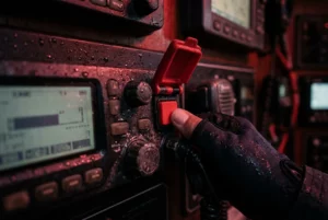
- Test the radio responsibly. Make a normal radio check on a suitable working channel as the rules in your area allow. Never press a DSC distress button during testing.
- Restore everything. Return every switch to its normal position and record the positions.
Write down anything that surprised you: a device that rebooted, a voltage lower than expected, a switch that was hard to find. Each of those is a fault you found at the dock rather than offshore.
A labeled one-page diagram for the crew
Draw the system on one page and laminate it. Put one copy at the nav station and another in the grab bag or with the ship’s papers. It should show:
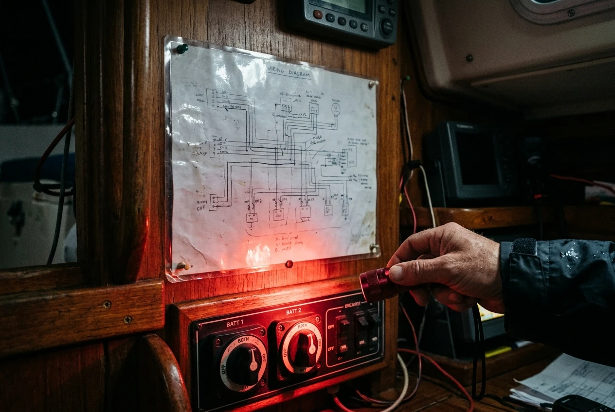
- Both batteries, their locations and their fuse ratings
- Every switch, with its name as labeled on the boat and its normal position
- Which loads are on the safety bus
- Three or four plain-language instructions: “House bank dead: set the selector to Emergency”, “Engine will not start: press and hold the emergency parallel switch”, and so on
- The location of spare fuses and the tool for changing them
Label the physical switches on the boat to match the diagram exactly. A crew member who has never seen the wiring should be able to follow the page at night with a torch.
Keeping it alive
An emergency system fails quietly. The battery self-discharges, a terminal corrodes, a switch gets moved, and nothing shows until you need it. A monthly check takes about ten minutes:
- Battery voltage. Measure the emergency battery at rest with a multimeter. A fully charged 12-volt lead-acid battery reads around 12.6 to 12.8 volts. For lithium, use the manufacturer’s figures. A low reading means the charger isn’t working.
- Terminals and connections. Look for green or white corrosion, loose lugs, heat discoloration, and damaged insulation. Tighten and clean as needed.
- Switch positions. Confirm each switch is where the diagram says it should be, and operate each one through its range once to keep the contacts clean.
- Charge source. Check that the solar controller, charger, or DC-to-DC unit shows it is charging.
- Bilge pump. Lift the float switch and confirm the pump runs.
- Backup devices. Check the handheld VHF, portable GPS, and power bank charge levels, and replace any spare batteries past their date.
- The diagram. Make sure it still matches the boat. Update and re-laminate it after any wiring change.
Write the date and the voltage readings in a small log kept at the nav station. A slow downward trend in the resting voltage shows up in the log long before it shows up as a failure.
Next: audit your critical loads
Once you design the second power path, the question is whether your list of critical loads matches the gear the boat actually carries. The essential sailing safety equipment checklist lists what a boat needs before it leaves the dock. Go through it with the electrical diagram beside you and mark which items depend on power, then check that each one appears on your safety bus or has its own battery.
This article was created with AI assistance and reviewed by a human editor.
Disclosure: This post contains Amazon affiliate links. If you buy through them, we may earn a small commission at no extra cost to you.
About The Author