Every marine navigation system answers three questions: where is the boat, how deep is the water under it, and what does the chart say is around it. Each answer comes from a different piece of hardware, and the cables and networks between those pieces decide whether the answers end up on one screen. This article follows a single signal path from the GPS antenna to the chartplotter to the fishfinder transducer, so you can see what each part contributes and what to check before you buy accessories for it.
What each part of a marine navigation system actually does
The marine navigation system components most boats carry fall into three jobs, and keeping them separate makes every buying decision easier.
- The GPS antenna and receiver work out position, speed over ground and course over ground from satellite signals. They know nothing about water depth or charts.
- The chartplotter holds or reads digital charts, takes the position it is given, and draws the boat on the chart. It also stores waypoints and routes and plots a course to them.
- The fishfinder and transducer measure what is under the hull. The transducer sends sound into the water and listens for echoes. The fishfinder (also called a sounder) turns the timing and strength of those echoes into a depth reading and a picture of the bottom and anything above it.
The chartplotter is the one device that displays all three kinds of information together. A position dot on a chart is only useful if the chart is current and the dot is accurate. A depth reading is only useful if you know what it is measured from. Because each answer starts in a different component, a fault in one place shows up in a specific way. A blank position field points to the GPS side, a missing depth reading points to the transducer side, and a missing chart points to the card or chart subscription.
Many modern units put all three jobs in one case. That changes the wiring, which a later section covers, but the three jobs stay distinct inside the box.
Where position comes from: the GPS antenna and its placement
A GPS receiver calculates position by measuring the signals it picks up from several satellites at once. It needs signals from at least four satellites for a position that includes altitude, and more satellites generally gives a steadier fix. The antenna is the part that has to see them, so what matters most is how much open sky it has.
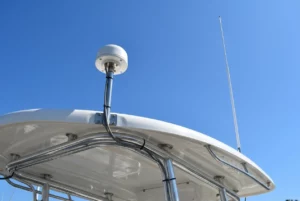
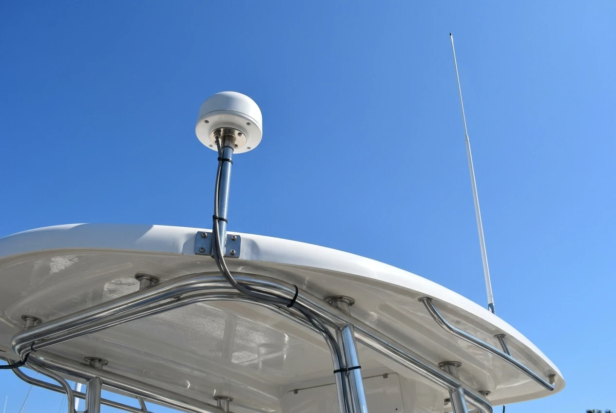
Many chartplotters have a receiver and antenna built into the case. That works when the display is mounted where the sky is visible, such as an open helm. It works poorly when the display sits under a hardtop, inside a cabin, or below a fiberglass overhead, because those structures weaken the signal. An external GPS antenna, often a small puck or dome, solves this by letting you mount the antenna in the clear and run a cable back to the display.
What the GPS side actually sends
The antenna and receiver output a stream of data: position, speed over ground, course over ground and the time. They do not output heading, meaning the direction the bow is pointing. Course over ground is the direction you are moving, so it is meaningless when you are drifting or stopped. If you want a heading line on the chart that holds steady at low speed, or you want radar or an autopilot to work properly, you need a separate heading sensor or compass on the network. Some GPS units contain a heading sensor, so check the specifications for that feature.
Placement matters more than price
Put an external antenna where it has a clear view across the whole sky, not just straight up. Keep it away from other transmitting equipment, since VHF antennas, radar and satellite communication gear can all interfere with a GPS signal when mounted too close. Avoid mounting it where a person standing, a rod holder or a bimini frame will block part of the sky. Mount it somewhere you can run the cable without sharp bends or a path through areas that flex, get wet or reach engine heat.
What to check before buying GPS accessories
- Whether your chartplotter has an input for an external antenna at all, and whether that input takes NMEA 0183, NMEA 2000, or a proprietary connection.
- What the antenna outputs and how it connects. A puck with a bare-wire NMEA 0183 output needs different wiring than one with an NMEA 2000 plug.
- The length of the antenna’s attached cable, and whether an extension is available or the cable should not be extended.
- Whether the antenna provides heading, or only position, speed and course.
- The mounting style: pole mount, flat surface, or rail mount, and whether the threads and brackets match what you already own.
The chartplotter as the hub that draws position onto a chart
The chartplotter is where the data meets. It receives position from the GPS receiver, whether inside it or outside, and places that position on a chart stored in its memory or on a card. Everything else it does, such as measuring distance to a waypoint, showing estimated arrival time or following a route, is arithmetic on position and the chart.
Charts are a separate purchase from the hardware
A chartplotter is a display and a computer. The charts it draws are data files, and they come from different publishers in different formats. A unit reads only the formats it was built to support, and some come with a base map that covers a region only roughly. Detailed coastal charts, lake charts with depth contours, and updates are often separate. Before you buy a card or subscription, confirm that your exact plotter model reads it. A card that fits the slot but is in the wrong format will not display.
The chart also has an age. Shoals move, buoys change, and new hazards get added. A chart in your plotter reflects the date of the data, not today’s water, so the plotter’s chart is a planning aid and not a replacement for watching what is in front of you.
The plotter’s inputs and outputs decide what it can listen to
A plotter typically has some combination of these connections:
- An NMEA 2000 port for sharing data with other devices on a network.
- An NMEA 0183 input and output, sometimes as bare wires on a power cable and sometimes through a dedicated connector.
- A proprietary or Ethernet-style network port, used to link to a sounder module, radar or another display from the same manufacturer.
- A power input, usually a twelve volt supply, and in some models a separate input for an external GPS antenna.
- A card slot for charts, and sometimes for saving waypoints.
The plotter is the unit that determines what accessories are compatible, because every other component has to connect through one of these ports. Check the port list on your model before anything else.
What to check before buying for the chartplotter
- The exact model number, and the ports listed on its specification page.
- Which chart formats and card types it reads, and whether the charts you want are available in that format.
- Whether it accepts an external GPS antenna, and if so, over which connection.
- Whether the power connector supplies enough voltage and amperage for the added devices you plan to connect.
- Whether a fuse or breaker is specified in the installation manual, and what size.
How the fishfinder and transducer feed depth data into the same screen
The transducer is the part in the water. It converts an electrical signal from the fishfinder into a pulse of sound, then converts returning echoes back into an electrical signal. The fishfinder measures how long the echo took to return, and because sound travels through water at a known approximate speed, it converts that time into distance. Stronger and weaker echoes show up as differences in color or intensity, which is how the display separates hard bottom from soft bottom and shows fish or structure in the water column.
Depth is measured from the transducer, not the surface
A depth reading starts at the face of the transducer. If you want the number to mean depth below the waterline, or depth below the keel, most units let you enter an offset. Without it, the number is still correct, but it may not be the number you need when judging whether you have enough water to pass over a shallow bar. Set the offset when you install, and decide deliberately which reference you want.
Transducer type and placement
Transducers mount in different ways: on the transom, through the hull, inside the hull shooting through the fiberglass, or on a trolling motor. Each style suits different hulls and boat uses, and each performs differently at speed. A transom mount works for many small boats, but it must sit in smooth, clean water. Turbulence and air bubbles beneath the face scatter the sound and cause dropouts, particularly when the boat is on plane. A shoot-through mount needs a solid hull without foam or air gaps in the path of the sound.
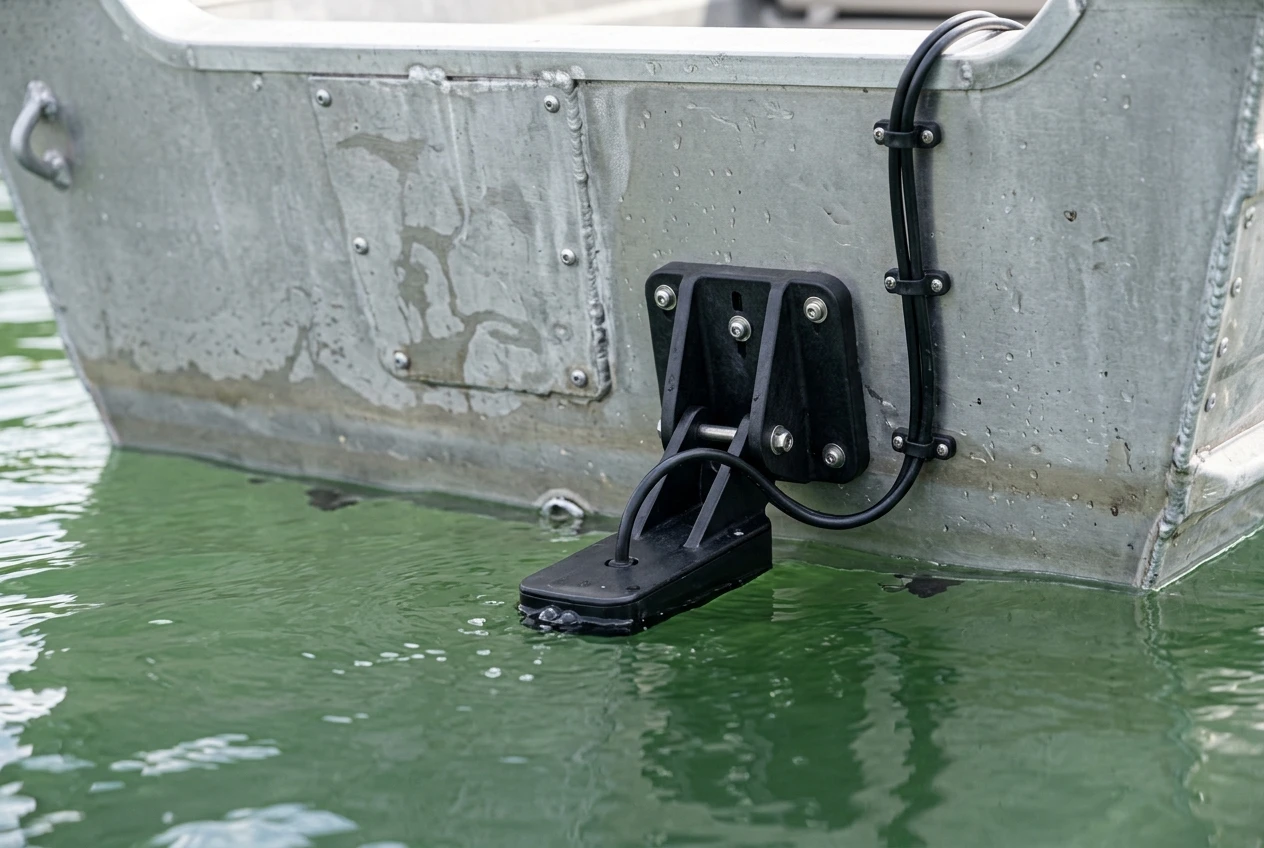
Frequency and cone angle also matter. Lower frequencies generally reach deeper and cover a wider area, while higher frequencies give more detail at shallower depths. Some transducers support several frequencies or a wide-band sweep, and the fishfinder has to support the same ones, so the transducer and sounder must be matched.
The transducer must match the sounder
This is the stage where mistakes are most expensive. A transducer plugs into the sounder with a connector that varies by manufacturer and sometimes by model. Even when a plug physically fits, the wiring inside may not match. A transducer designed for one brand’s sounder may not work with another’s without an adapter cable, and some will not work at all. The power rating and supported frequencies must also be compatible. Buying a transducer based on its performance alone, without confirming that it works with your exact sounder, is a common cause of returns.
What to check before buying for the fishfinder side
- The sounder’s model number and the transducers it lists as compatible.
- The transducer’s connector type, and the number of pins.
- The frequencies and power rating the transducer supports, and whether they match the sounder.
- The transducer’s mounting style against your hull type and how you use the boat.
- The cable length, since cutting and splicing a transducer cable can affect performance and is often discouraged by manufacturers.
- Whether the transducer includes a built-in temperature sensor, and whether your unit can read it.
Combo units versus separate boxes: what changes in the wiring
A combo unit puts the chartplotter and fishfinder in one case. A separate system uses a plotter display and a sounder module, usually a box mounted out of sight, that connects to the display over a network cable.
Wiring a combo unit
A combo has fewer connections. It needs power, a transducer, and optionally an external GPS antenna and a link to an NMEA 2000 network. Because the sounder is inside the display, there is no sounder network cable to run, and the depth data and sonar image reach the screen without leaving the case. The tradeoff is that the transducer cable has to run all the way to the helm display, and that the display has to be where you want the sonar picture too.
Wiring separate boxes
A separate sounder module lets you place the electronics near the transducer, which shortens the transducer cable. A network cable then carries the sonar data to one or more displays. This is useful on larger boats, or when you want the same sonar picture on a console display and a bow display. The cost is more components and more connections: a power feed for the module, the transducer connection, and a network cable with its own connectors, plus a network switch or a splitter if you have more than two devices.
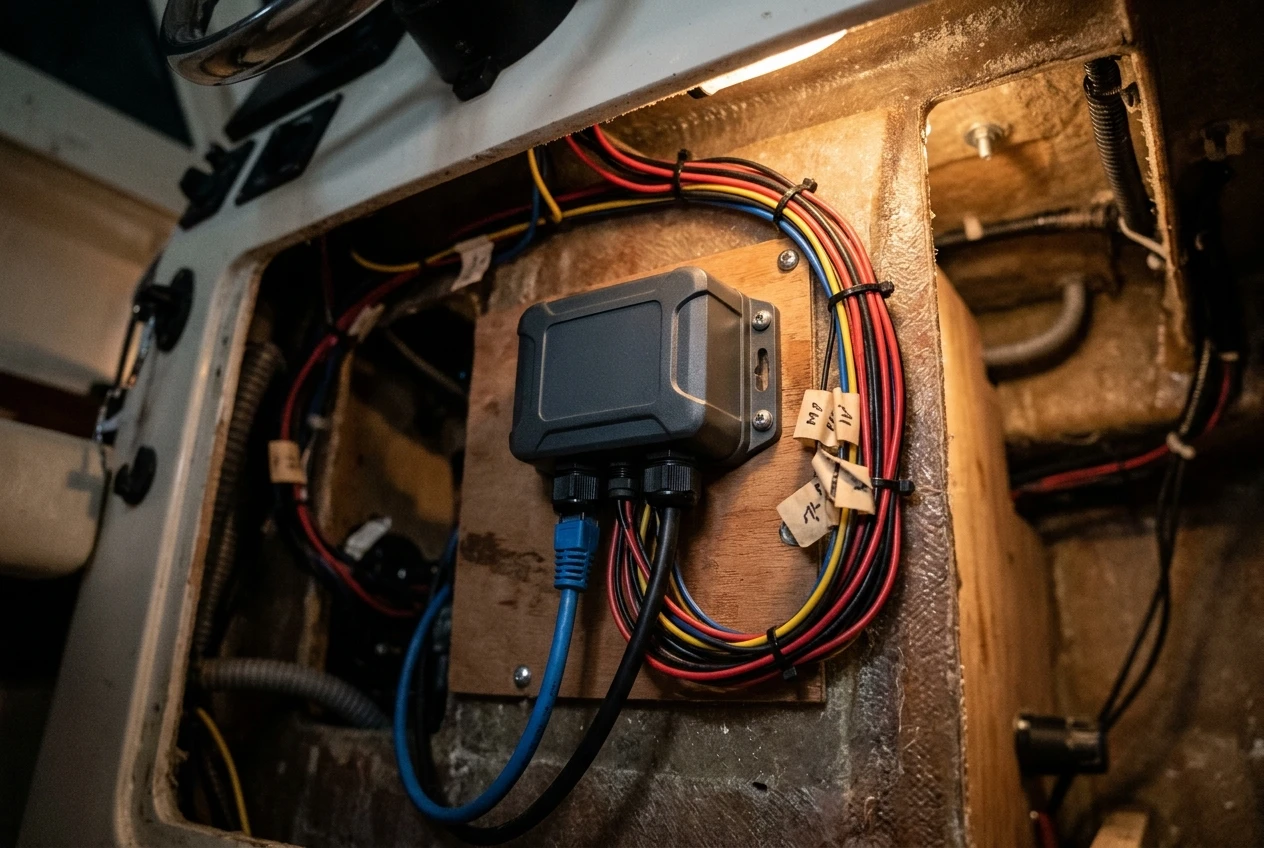
Sonar imagery is a large amount of data. It generally travels over the manufacturer’s own network, not over NMEA 2000, which is designed for small messages such as depth, position and speed. A depth number from a sounder can go over NMEA 2000, but the full sonar picture usually needs the faster proprietary or Ethernet-style link.
What to check before buying for this stage
- Whether you want one display or several, and whether the sonar picture must appear on all of them.
- The connector type and cable length for the sounder network, and whether the cable is sold in lengths that suit your boat.
- Whether the modules and displays you plan to combine are from the same manufacturer or are documented as compatible.
- Whether a network switch or splitter is needed when more than two devices share the network.
NMEA 0183, NMEA 2000 and proprietary networks: how the pieces share data
Once you know what each device produces, the question becomes how that data travels. Three kinds of connection cover most boats.
NMEA 0183
NMEA 0183 is the older standard. It sends text sentences over a simple pair of wires, from one device that talks to devices that listen. A GPS antenna might talk, and a chartplotter might listen. Each connection is generally point to point, so connecting several devices means running several pairs of wires or using a multiplexer. Standard speed is 4800 baud, which is slow, and a higher speed version exists for some equipment such as AIS receivers.
The common wiring problem is mixing up the wires. The talker’s output wires must connect to the listener’s input wires, and if the colors on two brands do not follow the same convention, the connection fails with no error message. The manual for each device shows which wire is which.
NMEA 2000
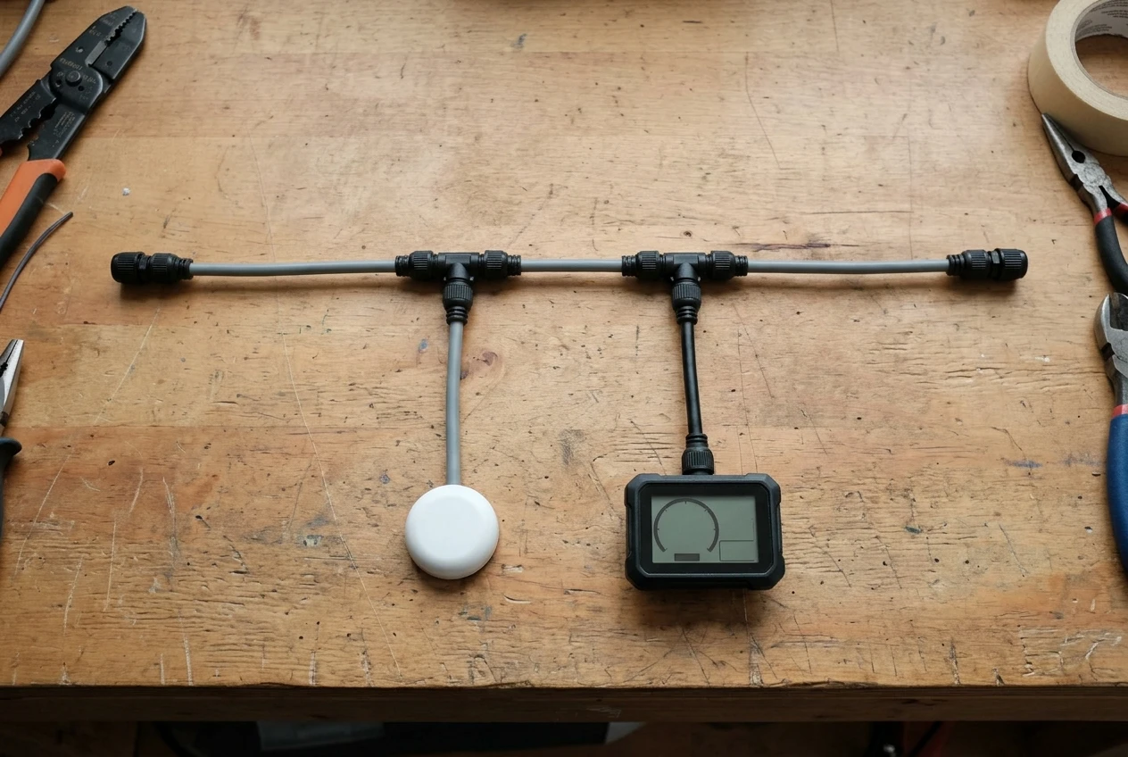
NMEA 2000 is a networked standard. Devices connect to a shared main cable, called the backbone, through short drop cables. Every device on the network can send and receive messages, so one GPS source can supply position to the plotter, an autopilot and an engine display at the same time. The network needs a terminator at each end of the backbone and a single power connection feeding the network. Drop cables have a maximum length, generally 6 meters or about 20 feet, and a network has a limit on how many devices it can support.
Because the connectors follow a few common styles, the pieces from different brands often fit together, but some manufacturers use their own connectors on networks that carry the same messages. Adapter cables exist for those cases. Before you buy, confirm the connector style on each device. Mini-C and Micro-C are the common sizes you will see named.
Proprietary and Ethernet-style networks
Manufacturers use their own networks for the heavier data, such as sonar imagery, radar, and sharing chart and waypoint data between displays. These links often use their own connectors and are not intended to be mixed across brands. If you plan to add a second display, a sounder module or radar, check which network that manufacturer uses and what the cables and any switch or adapter require.
What to check before buying for networks
- Which of the three network types each of your devices supports, and which ports are free on your plotter.
- The connector size and style on every device, since a plug that looks the same may be a different size.
- That you have a terminator at each end of an NMEA 2000 backbone and a power connection, if you are building a network.
- Whether the data you want to share, such as sonar images, can travel over the network you are planning.
- Whether an adapter or gateway exists between the two network types you need to connect, and what it converts.
Cables, connectors and adapters to check before you buy anything
Most installation problems trace back to a cable or a connector. A few habits prevent most of them.
Match connectors by name and by pins
Two plugs can look identical and differ in pin count or wiring. Look up the connector name and pin count in the manual for both ends. For transducers, confirm that the sounder lists the exact transducer model or connector, not only that the plug fits.
Plan the cable lengths with the route in mind
Measure the path the cable will actually follow, around bulkheads, through conduits and behind panels, not the straight-line distance. Add a margin for bends and for the slack needed at each end. A cable that is slightly too short forces an extension, and every added connection is a place for water and corrosion to enter. Extensions to power cables, in particular, can drop the voltage the device receives if the wire gauge is too thin for the length.
Power and grounding
Check the power requirements of each device and use the fuse size the installation manual calls for. Use marine-grade tinned copper wire, and seal connections against moisture. Where a network such as NMEA 2000 draws power from the boat’s battery, confirm that the power is switched appropriately so it does not drain the battery when the boat is idle.
Adapters
Adapters can convert a connector style, such as one brand’s network plug to a standard NMEA 2000 plug, or change the wiring for a transducer. They solve real compatibility gaps, but each one adds a connection. If an adapter is required for your setup, buy the one the manufacturer lists for those exact models. A generic adapter that fits physically may not carry the right signals.
Waterproofing
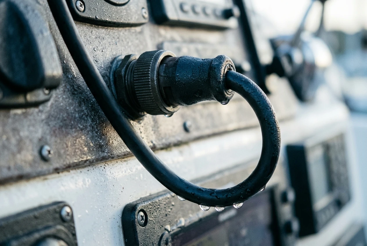
Connectors exposed to spray should have their seals fitted and locking rings tightened. Keep cable runs from low points where water collects, and route cables with a drip loop so water runs off before it reaches a connector.
Quick pre-purchase checklist
- Model numbers of the plotter, sounder, GPS antenna and any sensors, written down in one place.
- Connector name and pin count at each end of every cable you plan to buy.
- Measured cable routes, with extra length added.
- Power draw and fuse size for each device.
- Whether any adapters are required, and which are documented for those models.
A sensible order to build or upgrade your setup
Buying in a good order avoids paying for accessories that do not work with later choices.
- Choose the chartplotter first. It sets the ports, the network type and the chart formats everything else must match. Pick it based on screen size where it will be mounted, the ports it offers, and whether it includes a sounder.
- Decide how you will get position. If the plotter will sit somewhere with a clear sky view, an internal receiver may do. If not, plan for an external antenna that suits the plotter’s input, and mount it with a clear sky view.
- Choose the sounder and transducer as a pair. Match the transducer to the sounder model, to your hull and to how you fish or cruise. Settle on the mounting style before ordering.
- Add charts. Confirm the format works with your plotter, and choose coverage for the waters you use.
- Plan the network. If you have more than one device that shares data, decide between NMEA 2000, NMEA 0183, or the manufacturer’s own network, and list the backbone, drop cables, terminators and power connection you need.
- Add extras last. Heading sensors, additional displays, radar, AIS and engine data are easier to add once the base is working and you know which ports remain.
- Buy cables and adapters with the full list in hand. After the devices are chosen, you can compile the exact connectors and lengths, and buy them together.
Test the system at the dock before relying on it on the water. Confirm that position is updating, that depth reads sensibly, and that every device on the network is visible. A fault found at the dock costs a few minutes, and the same fault found offshore costs a lot more.
Browse the GPS accessories on the Marine GPS Accessories homepage to find antennas, cables and mounts that match your setup.
This article was created with AI assistance and reviewed by a human editor.
Disclosure: This post contains Amazon affiliate links. If you buy through them, we may earn a small commission at no extra cost to you.
About The Author